Rollicking Tracks (Part 2)
This description applies to ideal conditions. Unfortunately, in reality, all records are eccentric and warped, so the tonearm must accelerate and decelerate with each rotation. The elastic element of the cantilever deforms, causing the coils (or magnet) of the cantilever to deviate from the optimal position, resulting in asymmetrical EMF generation, which creates sound distortions.
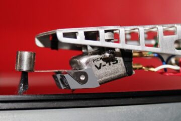
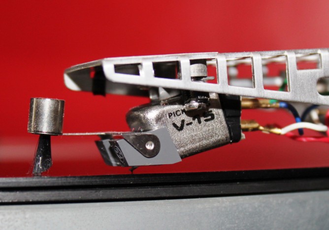
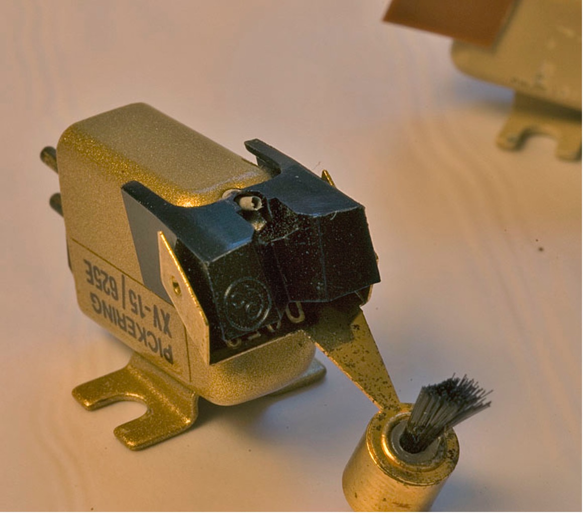 In the 1960s, aware of this issue, small brushes were invented and installed on the cartridge (either behind the needle or to the side) to help pull the tonearm instead of relying on the cantilever’s elastic element. Many thought the brush was for cleaning the groove. However, the bristles in the modulated groove began to tremble (and there are many bristles), transmitting this tremor to the cartridge body and degrading the sound quality. The brushes did not become popular.
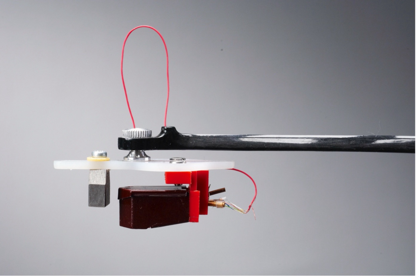
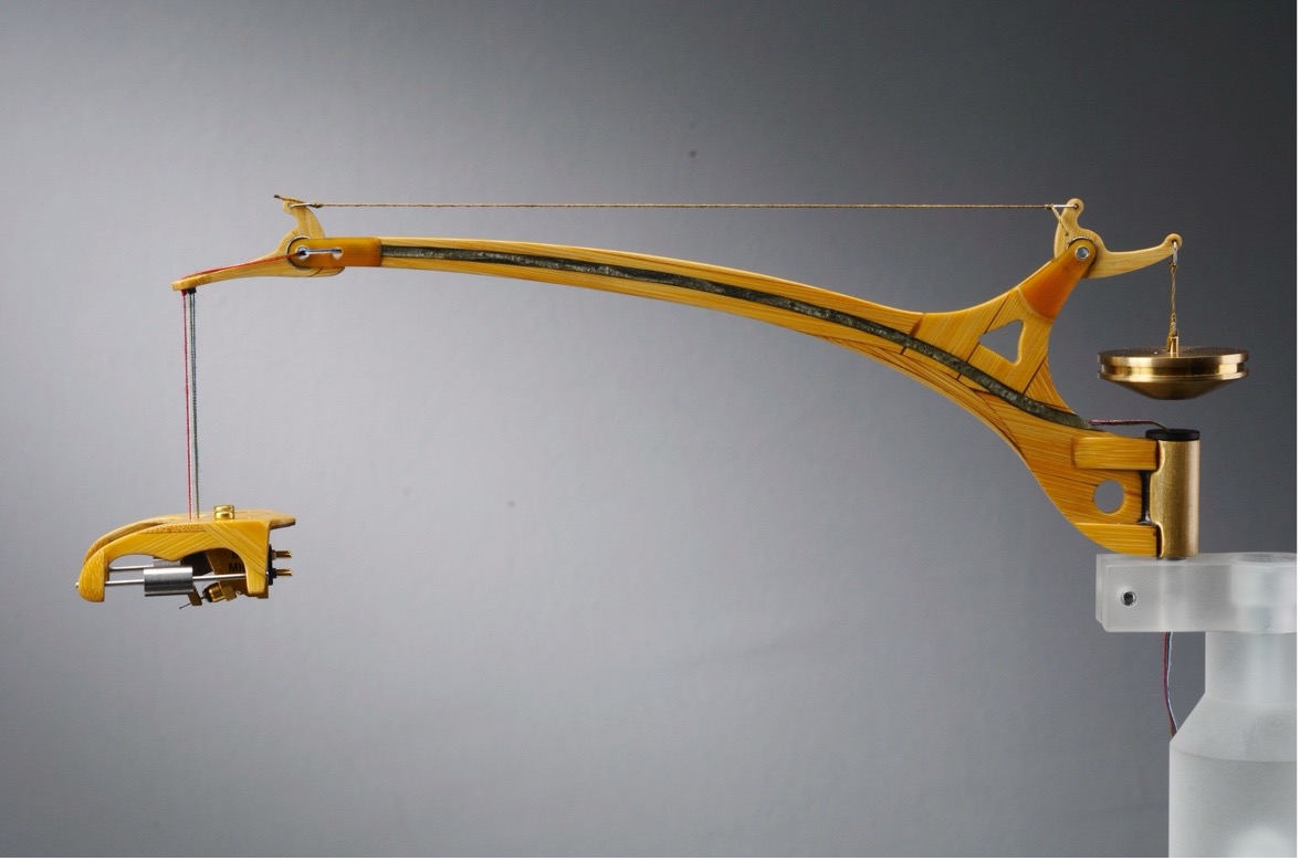
Specifically regarding the friction force between the needle and the groove walls. This force is crucial in calculating the necessary anti-skating force (the friction force multiplied by its lever arm gives the moment of force, from which, by reducing the lever arm to the point of application of the thread or spring force in the anti-skating system, we determine the required spring force or weight). However, this is only relevant for an unmodulated groove. In a modulated sound groove, the needle experiences impact loads (overload of 1000 G), making discussions about anti-skating somewhat futile. It’s unfortunate that a video showing the behavior of a cartridge suspended by flexible threads cannot be shown. In brief, the cartridge and its suspension system, with two tungsten counterweights totaling about 35 grams, are jerked forward and backward by the modulated groove and rotated around the needle at angles of plus or minus 30 degrees.
Try this experiment: Late at night, when the house is quiet, turn on just the turntable and place the needle on a rotating record. In most cases, you’ll hear a fairly loud sound produced by the combination of the cartridge and tonearm. This demonstrates how much vibrational energy from the sound groove is lost to the “acoustic” shaking of the cartridge and tonearm. However, don’t jump to conclusions about using rubber for the cartridge body and tonearm tube. Instead, focus on decoupling. Try this: place three small balls with a diameter of 0.2-0.3 mm on modeling clay between the cartridge and the tonearm’s head shell. Or use a multi-layer pad and replace the metal mounting screws with plastic ones, adjusting the tonearm height accordingly.
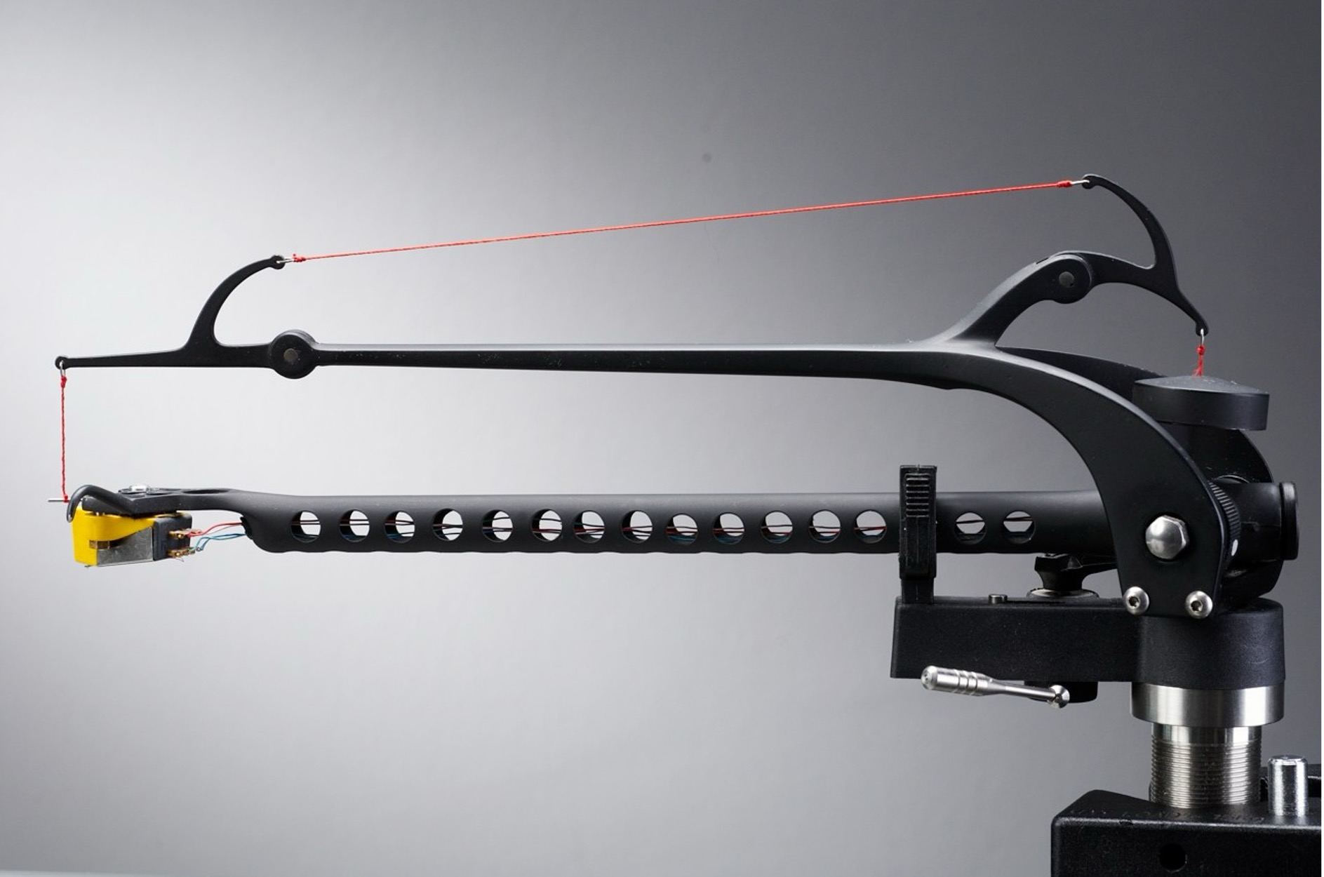
A clear example: Imagine the tonearm as a wind instrument: the cartridge holder as the mouthpiece, and the tonearm body as the body of a flute, oboe, or saxophone. The cartridge “blows” sound into the tube, which acts as a resonator to amplify them and… returns them with a delay to the cartridge body. Phase and intermodulation do not improve. If omnipotent RUMBLE penetrates into the tonearm tube, the situation worsens. A tube with holes or a tonearm with a “P” shaped cross-section can drastically improve matters.
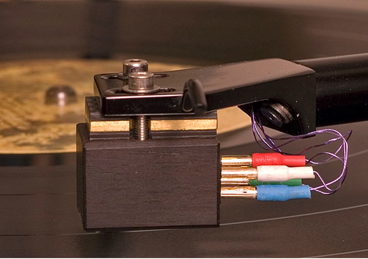
Internal tonearm wires are a delicate matter. At best, only the brand of wire and connectors is specified. Here’s some interesting data: The ratio of the cross-sectional area of the coil wire in the cartridge to internal tonearm wire is 1:55 for CARDAS and 1:75 for VDH. Copper offers 15 times less resistance than tin, and 35 times less compared to solder. Therefore, each unnecessary solder joint, especially with a low-power signal, introduces a detrimental impact on the audio signal. Let’s list the signal connections from the cartridge pins to the preamp or step-up transformer: the pin connector on the cartridge, short wire solder joint, solder joint to the head shell pin, head shell connector, internal tonearm wire pin connector, internal tonearm wire solder joint, solder joint at the tonearm base pin, tonearm base connector, solder joint to interconnect pin, interconnect wire, solder joint to the interconnect pin, interconnect connector (and for tonearms with a removable tube, one more connector). It’s possible to run a wire directly from the cartridge pins (using a silicone tube to attach the wire to the pin) to the interconnect connector pin! Extremists might use only two internal tonearm wires, halving the conductors inside the wire (since each conductor inside these wires is coated with varnish, known as litz wire), thus reducing the cross-sectional area ratio between the coil wire and internal tonearm wiring. It is advisable to install insulating washers inside the tonearm with four (or two) holes through which to thread the internal tonearm wires. A discussion about head shells and pivot points will come next time…